
This week's post is inspired by a tweet by Brenda Puech about the difficulties faced by wheelchair users in negotiating footways which have poorly arranged and steeply sloping vehicle crossings to private property.

Twitter is great at feeding me ideas for posts and in this case, I think Brenda has raised an excellent point which is (mostly) easy to deal with, so a big thank you her.
So, to the basics. We are dealing with "vehicle crossings" which is dealt with under S184 of the Highways Act 1980. It is a power that the local highway authority has where someone needs to (or already is) taking a mechanically propelled vehicle over a kerbed footway or verge. (don't worry, I am not going to describe the detail of S184!) I would add, that we can also be dealing with private roads meeting the highway and a vehicle crossing could even be the norm for side roads meeting other roads, the so-called continuous footway or "blended junction".
The provision of a vehicle crossings is a power rather than a duty and there is no automatic right for someone to have one installed. For example, if we have an accessible bus stop, putting a vehicle crossing through the middle of the waiting area will remove accessibility and so the highway authority has every right to decline a request for a vehicle crossing. It is quite useful to have a policy in place to help deal with applications though.
So, to the point. What makes a good vehicle crossing? In fact, what makes a good footway in the first place? For the detail, you can refer to "Designing for Walking" which is free to download guidance from the Chartered Institution of Highways & Transportation (CIHT); Section 6.3.1 covers vehicle crossings and Section 4 some more general matters on footway design. For this post, we are mainly interested in the crossfall of the footway and what happens with levels along the line of travel, as well as footway width.
The basic point of a vehicle crossing is to allow people to drive between the carriageway and private property and so most of the time, this involves dropping the kerb from a "full height" to a "dropped" kerb. There are lots of different kerbs out there, but in most situations we will have kerbs with a "face" (height about the carriageway surface) of around 100mm to 125mm (yes it varies). We will then have a pair of transition (ramped) kerbs which take us down to the dropped kerbs which will have a face of about 15mm to 25mm. The face on the dropped kerbs is useful as it helped visually impaired people know that they are at the edge of the footway (as well as "feeling" the slop to the dropped kerb).
 In usual circumstances, footways will have a crossfall of around 1 in 50 (2%) from the back to the kerb. This is needed to make sure water drains off the footway into the carriageway as standing water would be an ice risk in the winter and not very nice to walk through at other times. If the footway is laid in asphalt, the skill of those installing the surfacing will be telling in terms of water still getting trapped if the surface isn't laid flat enough - I am starting to think we should machine-lay asphalt footways and strengthen them to enable machine lay (structural design of footways is a subject for another day).
When it comes to dropping the footway for the vehicle crossing, many people will just increase the gradient to cope with the lower kerb. For example, a 2m footway with a full-height kerb face of 125mm which drops to 25mm could go from a 1 in 50 crossfall to 1 in 14. For many people, this change in gradient is difficult to cope with and for everyone else, it is like trying to be a mountain goat!
 Imagine if there are vehicle crossings like this for each house you pass, each going from a 1 in 50 to a 1 in 14 crossfall and back each time - how very tiring to walk along and of course a much greater problem for those using wheelchairs, pushing buggies and so on. The other thing with this arrangement is that at the rear of the footway, the level along the direction of travel stays the same, but at the kerb, there is also the slope down to the dropped kerb to think about. The stock ramp kerb is 914m long (3 feet) and the transition provided is 100mm, which gives slope of 1 in 9. When we consider the usual pedestrian dropped kerb gradient is 1 in 20 (1 in 12 maximum), then 1 in 9 is also significant. The narrower the footway, the greater the problem too.
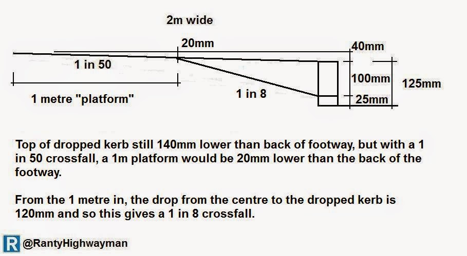 So, how can we make things easier? CIHT recommend that a level "landing" of at least 1m is required. In practice, this means keeping the rear 1m of the footway at 1 in 50 and then only sloping the front part down. With our 2m footway example, this means that the front part of the footway (1m) would have a gradient of 1 in 8 which is steep for pedestrians to use, but no effort to drive over (at a suitable speed).
 The reason for the 1 metre platform is that it is seen as the minimum unobstructed width needed to walk along, use a wheelchair or push a buggy. This might be fine with the odd vehicle crossing, but where there are lots, then we quickly end up with an effective footway width of only one metre by default and it is no good if people want to walk side by side.
There are other options available to us. Where there are multiple vehicle accesses to property, it might be better to drop a complete length of footway with gentle slopes at each end (which will need thought with laying the kerbs right at each end - remember a transition kerb is a 1 in 9 gradient). It does mean the levels at the rear of the footway need to be looked at as these will need to be dropped too which can mean doing work on the "private" side to get it working right.
 CIHT also suggest using one of my favourite kerbs, known as the quadrant kerb. To be honest, nobody on site calls it a quadrant, it is affectionately known as a "cheese" because of the passing resemblance to a lump of Edam! The kerbs are available in two stock sizes (the 455mm one being more robust) and is compatible with standard UK kerbs. It is possible to get much larger ones made in natural stone - I have used 1m radius ones to form dropped kerbs at pedestrian crossings in the past.
The quadrant kerb used in our 2m wide footway example gives another half a metre of usable footway and the other advantage is that people need to be really careful driving over them - moving slowly which is a good thing as far as I am concerned.
 The quadrants are installed as in the diagram to the right and they allow most of the footway to stay at he same gradient. The area between the quadrants is then ramped down to the dropped kerb level. The use of quadrants is not always something people like because of the risk of someone tripping over them, but I would argue that people tend to walk in from the kerb because of traffic and a wider usable footway is the bigger concern.
 There is a variation on using quadrants with a little slope and that is using special ramped kerb units. The photo to the left show a unit about 300mm wide which with the special transition kerb go to form the ramp wholly within the kerb line. The normal kerb in the photo onto has a kerb face of about 50mm and so the slope on the kerb is gentle for drivers to negotiate. This arrangement is often seen elsewhere in Europe, although kerb faces are also often lower than in the UK which makes the transitions easier - perhaps we should lower out standard kerb units? Of course, we don't have to lay kerbs with a 125mm kerb face, we can use standard units to lay them a little lower, but it is an issue which people don't seem to think about.
 A nice way to accommodate vehicle crossings is by using a grass verge. The main part of the footway can be left with the gentle crossfall and the front of the vehicle crossing can be ramped within the line of the verge. The use of verges is also nice because we can plant trees and install lighting columns and signs without creating clutter for those walking.
I suppose for some people, the ultimate in providing level surfaces is the establishment of a shared space scheme. I will be blogging about the concept later this year, but it is worthy of a mention here. My caveat is that I only think the idea works in very specific circumstances of vehicle access and low speed (I mean walking pace), but that will be covered another day.
 The photo on the left is a little one-way street which is under construction at the moment. The reddish area is the "carriageway" and the grey area the "footway". I state in quotes because the whole thing is a level surface. While not a boundary to boundary treatment in the same materials, this is a form of shared space and its success will be known in time. From a vehicle crossing point of view, there were no levels to accommodate and so for the "footway" area is really flat and easy to use (this would be a similar case with access taken from a speed table, although a small kerb upstand would normally be used).
The entire area is built to carriageway standards and so the "footway" can be overrun. The important point here is that the parking is designed into the scheme so that anyone parked on the "carriageway" will block the street to vehicles and anyone parked on the "footway" is at risk of a parking ticket as this is a London site - time will tell on this (developer designed) site.
Whatever type of vehicle crossing is used, it should be constructed to take vehicle loading. It doesn't necessarily need to be designed to take a 40 tonne lorry, but it should be substantial enough to take regular use by light vehicles. I don't think we construct our footways that well in the UK (at least outside city centres) and would advocate building them to a better structural standard anyway.
 To get things really right I want to describe the tricky issue of "accommodation works". When I was a junior engineer doing mainly maintenance works, I was fortunate to work for a really good principal engineer who considered maintenance work as something rightly needing the same care and attention as new build. When it came to a footway reconstruction scheme, he was always eager to get the levels right to best serve pedestrian comfort and this has stayed with me over the years.
Accommodation work is the practice of entering private property and (with agreement) adjusting levels. This means that footway levels can be gotten spot-on for maximum improvement those walking. So fanatical were we all about accommodation works, that around 10% of a footway renewal budget was given over to the work. The image from Google Streetview above is a footway scheme I did about 15 years ago. The "joined" on strip of concrete is actually on the private side of the highway boundary and allowed the rear of the footway to be laid level. In the most extreme case, we relaid about a third depth of someone's driveway to get the levels to work properly. Getting this right takes time and effort, but it is worth it.
 And finally (hooray I hear you scream) I have to mention cycling. In thinking about situations where people need access over a cycle track, much of what I have written applies because we want to keep the riding conditions comfortable.
The photo on the left shows Old Shoreham Road in Hove which has a stepped cycle track for each direction; that is the cycle track is lower than the footway and the carriageway is lower than than the cycle track; with kerbs doing the stepping down.
What this has meant for those walking is the kerb height between the track and the footway is quite low and so the vehicle crossings don't need much ramping down to the track which gives good levels of comfort for walking. The cycle track kerb height is also low, so the creation of vehicle crossings over it are not obvious as one cycles along. A good example of cycling infrastructure assist those walking and cycling.
The basic point of a vehicle crossing is to allow people to drive between the carriageway and private property and so most of the time, this involves dropping the kerb from a "full height" to a "dropped" kerb. There are lots of different kerbs out there, but in most situations we will have kerbs with a "face" (height about the carriageway surface) of around 100mm to 125mm (yes it varies). We will then have a pair of transition (ramped) kerbs which take us down to the dropped kerbs which will have a face of about 15mm to 25mm. The face on the dropped kerbs is useful as it helped visually impaired people know that they are at the edge of the footway (as well as "feeling" the slop to the dropped kerb).
In usual circumstances, footways will have a crossfall of around 1 in 50 (2%) from the back to the kerb. This is needed to make sure water drains off the footway into the carriageway as standing water would be an ice risk in the winter and not very nice to walk through at other times. If the footway is laid in asphalt, the skill of those installing the surfacing will be telling in terms of water still getting trapped if the surface isn't laid flat enough - I am starting to think we should machine-lay asphalt footways and strengthen them to enable machine lay (structural design of footways is a subject for another day).When it comes to dropping the footway for the vehicle crossing, many people will just increase the gradient to cope with the lower kerb. For example, a 2m footway with a full-height kerb face of 125mm which drops to 25mm could go from a 1 in 50 crossfall to 1 in 14. For many people, this change in gradient is difficult to cope with and for everyone else, it is like trying to be a mountain goat!
There are other options available to us. Where there are multiple vehicle accesses to property, it might be better to drop a complete length of footway with gentle slopes at each end (which will need thought with laying the kerbs right at each end - remember a transition kerb is a 1 in 9 gradient). It does mean the levels at the rear of the footway need to be looked at as these will need to be dropped too which can mean doing work on the "private" side to get it working right.
The quadrant kerb used in our 2m wide footway example gives another half a metre of usable footway and the other advantage is that people need to be really careful driving over them - moving slowly which is a good thing as far as I am concerned.
I suppose for some people, the ultimate in providing level surfaces is the establishment of a shared space scheme. I will be blogging about the concept later this year, but it is worthy of a mention here. My caveat is that I only think the idea works in very specific circumstances of vehicle access and low speed (I mean walking pace), but that will be covered another day.
The entire area is built to carriageway standards and so the "footway" can be overrun. The important point here is that the parking is designed into the scheme so that anyone parked on the "carriageway" will block the street to vehicles and anyone parked on the "footway" is at risk of a parking ticket as this is a London site - time will tell on this (developer designed) site.
Whatever type of vehicle crossing is used, it should be constructed to take vehicle loading. It doesn't necessarily need to be designed to take a 40 tonne lorry, but it should be substantial enough to take regular use by light vehicles. I don't think we construct our footways that well in the UK (at least outside city centres) and would advocate building them to a better structural standard anyway.
Accommodation work is the practice of entering private property and (with agreement) adjusting levels. This means that footway levels can be gotten spot-on for maximum improvement those walking. So fanatical were we all about accommodation works, that around 10% of a footway renewal budget was given over to the work. The image from Google Streetview above is a footway scheme I did about 15 years ago. The "joined" on strip of concrete is actually on the private side of the highway boundary and allowed the rear of the footway to be laid level. In the most extreme case, we relaid about a third depth of someone's driveway to get the levels to work properly. Getting this right takes time and effort, but it is worth it.
The photo on the left shows Old Shoreham Road in Hove which has a stepped cycle track for each direction; that is the cycle track is lower than the footway and the carriageway is lower than than the cycle track; with kerbs doing the stepping down.
What this has meant for those walking is the kerb height between the track and the footway is quite low and so the vehicle crossings don't need much ramping down to the track which gives good levels of comfort for walking. The cycle track kerb height is also low, so the creation of vehicle crossings over it are not obvious as one cycles along. A good example of cycling infrastructure assist those walking and cycling.
When I was growing up vehicle crossings had some chamfered kerbs & a couple of quadrant style transition kerbs and an effectively level footway. http://postimg.org/image/8kcky2sdt/
ReplyDeleteIn the intervening period vehicle crossings have developed to give vehicles effectively level access but bringing the issues you've highlighted to people travelling along the footway.
I had a chat with a local engineer about the design of the vehicle crossings & was told the modern design is standard as they give people with mobility issues the ability to cross the road at a variety of informal places rather than just designated crossing points and allow vehicles to leave the carriageway at a higher speed reducing the likelihood of a turning vehicle being rear-ended.
Is that right?
While a ramped vehicle crossing might be useful for some people with mobility impairments, it is not universal. With an upstand of around 25mm, this can be pretty useless for many people using many mobility scooters and wheelchairs for example; in other words, if there are desire lines to be accommodated, then we should provide for the for all people.
DeleteAs for the rear shunt issue - what is an appropriate speed to enter an access at? Seems spurious to me.
I'm very late to the commentfest here, but I think this blog post is evergreen content. (Thanks!)
ReplyDeleteI note your statement that provision of a vehicle crossing is a power not a duty, and I am wondering: what is the situation with regards to dropped kerbs for other non-motor-vehicle purposes? For example, provision for wheelchair users, people with mobility scooters, riders of heavy bicycles?
It's an interesting point which was probably not considered in the legislation as such, but a local authority does have the powers to put in a dropped kerb for those sorts of purposes - I have installed dropped kerbs on occasion for similar types of reason (a common one being access to bin stores for wheeled bins).
DeleteIn Cranebridge Greenways are being cut by roads for housing developments (A10 cyclepath, Clay farm, Airport). This is to ram home the lower status of active travel and cause a giveway to motor vehicles. Kerbstones cutting the greenway and/or lights are used to do this. What new design guides / laws can be used to restore the level and the priority to what it was?
ReplyDeleteI guess it's a look at LTN1/20 - any location examples?
Delete