Sunday, 29 January 2017

Kerb Your Enthusiasm: Stepped Cycle Tracks

I blogged about kerbs over three years ago and this week, I return to the subject (albeit briefly).

In truth, this is more of an update on kerbs and their use with stepped cycle tracks (from a UK perspective). Believe it or not, there have been some UK kerb developments, but I think we are still missing tools which would really make things easy (which the Dutch already have been using for years).

You might want to get up to speed by reading my previous post, but the key reasons we use kerbs are as follows;
  • Retain the edge of the top layers of a pavement (I use this in the structural sense of a carriageway, footway, cycle track etc, rather than the often used substitution of footway),
  • A demarcation between different areas or uses of a highway - the obvious here is a kerb between a carriageway and footway,
  • To provide a check or channel for surface water management,
  • To provide restraint to prevent vehicles leaving the carriageway
In designing cycle tracks, these principles hold, because we are ultimately building little roads for cycles and so we need to use kerbs as part of that process.

Using kerbs as restraint to prevent vehicles leaving the carriageway is clearly very important as is providing demarcation. The way in this can be achieved varies considerably, but in general, it leads to the position that kerbs next to motor traffic are there to stop (or at least discourage) encroachment into cycling space and that kerbs use to demarcate space from pedestrians should be forgiving.

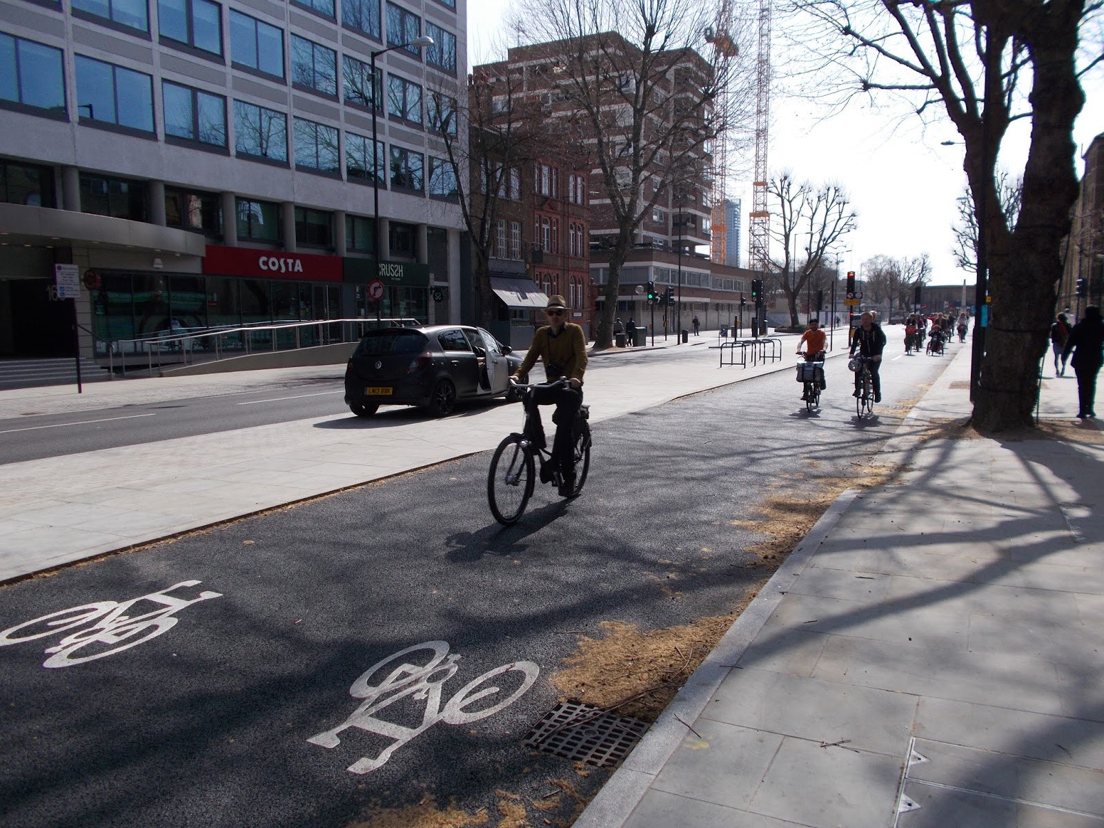
Stopping encroachment by traffic is a matter of degree, and depends on the height of the kerb face presented to the carriageway (as well as the amount of lateral space between the carriageway and the track). The usual type of kerb found edging a carriageway in the UK will be half-battered (HB2 type) with a nominal "face" (or height) of 100 to 125mm;


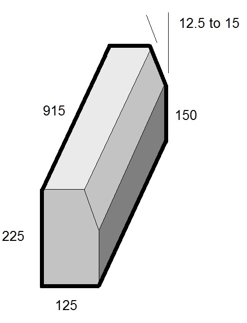
As common with UK kerbs, the unit is 915mm long (3 feet). The overall height of the kerb is 255mm, it's 125mm wide and on the face, the top section is battered back from the vertical by around 12.5 degrees. If you used this type of kerb by the carriageway to support a stepped cycle track, there is no particular issue until we get to driveways, where we would drop the kerb height down to 25mm (using a transition kerb and a bull-nosed kerb; a bull-nosed kerb is square rather than battered with a rounded "nose" at the traffic side).


The traditional way of doing this in the UK leads to the path dipping to meet the low kerb. I've explained ways of dealing with this issue for footways before and the same techniques could be employed with cycle tracks;

The image above shows the typical way we have dealt with transitions to driveways on the left. If this is a cycle track, it leads to a very uncomfortable experience, especially the further right we get. For people using tricycles, the approach is highly likely to tip them over. The image on the right shows a buffer strip within which the transition is made, but in which the track is kept with a nice and constant shallow crossfall (1 in 50 works well for drainage); this pitfall can be seen on this example from Leicester below;


The buffer zone can be as wide as we like - indeed, if it is a couple of metres, then it can be grassed and planted with trees which gives lots of protection from the traffic and in the event anyone falls off their cycle, it's into a verge and not live traffic. Such a wide buffer might not be possible and really, anything getting down to half a metre would need a different approach using quadrant kerbs.

This is all well and good, but relies on being a bit clever with UK kerbs. What we really need is a UK version of the Dutch "inritbanden" kerb to provide a transition from carriageway to stepped track;


The photo above is not of a stepped track, but the kerbs I'm interested in is the row by the carriageway edge which ramp up to footway level. It would be very simple to make these to UK dimensions, but they do of course still rely on using a narrow buffer within which to lay them.

In those tight areas, we might feel that the buffer is a luxury we can do without in terms of maximising track width. In these cases, if we are trying to keep the track nice and level, we have two options. First, we can keep the track at one level and use ramped kerbs from the carriageway to the track as used here in Cambridge;


The kerb next to the carriageway is called the "Cambridge Kerb" and is made by Aggregate Industries. The kerb is about 35mm high and is sloped. From a cycling point of view, it's easy to ride up and down at a shallow approach and so it's forgiving. It's also easy for drivers to do the same thing and so it is less useful in preventing incursion.

The other way to do it is with standard kerbs, but keeping the kerb face lower than the standard 100-125mm and dealing with transitions over a longer distance than the usual single (915mm) kerb. A bull-nosed kerb with a nominal 65mm face gives a reasonable amount of protection from moving traffic and if we transition up and down to the 25mm kerb at driveways over two kerbs (1.8m), we get very gentle level changes. Even close to the kerb, the ride is good and the change in level negligible, even on a tricycle;


It's hard to make out, but above is a track with a constant level at the rear and a low (65mm) bull-nosed kerb at the front. Transitions from the higher bull-nosed kerb to the 25mm at driveways occurs over 1.8m. It's a compromise, but works well. It's also rather complicated to design and so needs a bit of effort to get it to work!

With stepped tracks, there is always a possibility of drivers getting onto them. The layout using bull-nosed kerbs is less likely to be encroached on under normal traffic speed, but at low speeds, drivers can mount the track reasonably easily, especially at the driveways. This can be useful in the event they need to move out of the way to let an emergency vehicle through, but it is very tempting for people delivering to park there.

So much for the carriageway side, what about the other side of a stepped track? We are starting to see some fairly decent cycle tracks being built in the UK, but we often struggle where they are next to a footway. We cannot treat cycles like motor vehicles here and provide a vertical kerb to prevent incursion onto the footway. Well, we could, but high kerbs (over 60mm) will catch pedals (as on the photo below) and low vertical kerbs can grab wheels.


We've often deal with the demarcation between cycle tracks and footways with a special 200mm by 200mm block with a raised centre section of up to 20mm (with sloping sides) to act as a tactile warning to visually impaired people (see the photo below). Unfortunately, it's use often goes hand in hand with acres of tactile paving which is a pain for people walking and cycling;


The advantage of this demarcation block is that people using cycles for mobility purposes (such as a hand-cycle) can easily bump over the block to leave the cycle track (at a shop for example). Personally, I prefer a step down to the cycle track as it helps define clear space.


The photo above shows a stepped track, but the kerb at the rear is vertical and so can grab wheels and can be difficult for people to bump over, so we need something better.


The photo above shows a Dutch cycle track and the demarcation kerb has a slope of about 30 degrees and so meets the objective of being forgiving and can be bumped over if needed.

In the UK, we don't have this profile, we have a full-battered or splay kerb with a 45 degree slope;


It's clearly more forgiving than a vertical kerb, but with a 75mm face, it's still a pedal catcher. I don't recommend bouncing up and down such a kerb too much, it's still too steep, but it's fairly forgiving. Some have used this type of kerb, but buried it deeper to get a lower face;


The trouble is, this is still a bit of a wheel grabber because the angled area is just too narrow. The Cambridge kerb would provide a perfect solution here, but it's only available as a full-height (255mm) kerb which is over the top for cycle traffic and (I understand) requires a minimum order of 1000 metres! A half-height Cambridge kerb (150mm) would be the idea solution.

However, we do have another kerb we can play with and it's off the shelf. Going back to the half-battered kerb I mentioned earlier, it is available in different sizes, including a 150mm high variant (HB3);


It has the same profile as the full height kerb, but it has been shrunk to give less on the vertical part on the bottom. This profile is more usually used on bridges where the half-battered profile is wanted, but where there is no need for a deep kerb (as the surfacing goes onto the bridge deck rather than having a thick road construction). We don't use it like this for cycle tracks, we need to apply some lateral thinking;


By turning the kerb through 90 degrees and laying on its back, we get a gentle and very forgiving slope with an overall upstand (or step down) of about 35mm;


One disadvantage with using this kerb in this way is that because the elements are straight, we cannot lay it to tight radii. Actually, this is a distinct advantage as it stops designers proposing stupidly tight corners! You can just about get away with an internal radius of 8 metres and so it keeps the track flowing nicely.

When we put a decent and forgiving kerb at the rear of a stepped track and the best traffic deterring kerb we can at the front (with a buffer if possible) then I think we can provide some pretty decent infrastructure. The other advantage of stepped tracks is that we can take space from the carriageway by building up layers, rather than digging down and this is great because it generally avoids the need to get involved in the costs and effort of dealing with buried utilities. Therefore, they represent a pretty good way to retrofit our streets. But, details are everything, including how we use the humble kerb.

Saturday, 21 January 2017

Tough Tactiles

The wonderful thing about technology is that thanks to mobile phones, I've generally got a camera with me. The downside is I take photos of boring stuff and then blog about it!

This week, I was running early for a meeting in Westminster and so went for a walk to kill time and I spied some footway works being undertaken. I took the following photo of some tactile paving.


The works on Victoria Street were a little further along and it looks like this paving was done last year, but no matter, there is learning here. So what is wrong?

The first point to make (or repeat if you're a regular reader) is exactly who is this paving for? It's essentially to provide guidance and warning information for visually impaired people. The full detail is on my post here. This style is called "blister" paving and is is used to help people find the edge of the footway at a pedestrian crossing point. Such crossings need to be flush with the carriageway surface to assist people on foot, wheelchair/ mobility scooter users etc and so the paving is needed because some people may not realise they are walking into the road.

Current UK guidance talks about "controlled" and "uncontrolled" crossings; the former are zebra and signal controlled crossings (green men), the latter everything else. My photo is of a controlled crossing (signal-controlled junction where the guidance states that the tactiles should be red in order to provide a colour contrast with the surrounding paving. There is relaxation in a conservation area situation where red wouldn't be in keeping and in that case, a contrast should be provided. In this case, we have light grey paving and light grey tactiles and so it fails the contrast requirements.

Next, we have the shape. Current guidance in this situation would have at least 3 rows of tactile paving (1200mm) behind the kerb to reduce the risk of someone stepping over it/ not detecting it and realising it's an "in-line" crossing and a "tail/stem" 3 tactiles wide going away from the dropped kerb (forming an 'L' shape) to help people locate the push button. The image below is from the guidance.


Now, there was a consultation in the second half of 2015 for some interim changes to the guidance which I commented on at the time. In this situation, the changes would allow the back of the tactiles to be cut into a curve parallel at the front if on a kerb radius. The proposed changes did not remove the requirement for the stem and they did not propose a change to the 1200mm depth of paving at in-line crossings such as this. At the time of writing this, no official guidance changes have been made.

I suspect that the reason that 800mm without a tail was selected relates to Transport for London's Streetscape Guidance (it's nearly 32Mb!). Part E of the guidance deals with crossings and in terms of tactiles, it notes departures from the National guidance on p132 in terms of radii where the 800mm constant width can be used to avoid large areas of tactiles; that contrast is more important than colour; that it's own research with University College London in 2010 shows that 800mm is readily detectable and the crossing of tails can be confusing. Importantly, TfL advocates proper recording of why a layout would depart from National guidance.

My personal view is that TfL may be right and they certainly have the resources to challenge the National position (they did on cycling infrastructure), but the designer of the tactiles in my photo has certainly ignored the contrast requirement! As ever, there is conflicting views on how tactile paving should be used and the risk for users is that consistency gets eroded. Ultimately, if guidance is updated with the support of user groups, I am more than happy to follow it! I digress.

The issue of tactile paving on radii is also problematic because it means the grid pattern of the blisters can be mistaken to mean the crossing is perpendicular to the intended direction. The photo below shows the intended crossing direction with the green arrow. The red arrow could have people walking out into traffic.


There is debate as to whether visually impaired people use the blisters to align themselves (and I mean debate from users; other people's views are a distraction). Since I last wrote about tactile paving, I undertook some accessibility training and part of it was delivered by someone with a guide dog (who sometimes uses a long cane). As well as classroom discussion, there was a practical walk around town.

On the subject of blister paving, the trainer's view was that it was useful for him to know he was at the edge of the road, but as he was listening to traffic position, the orientation didn't bother him. He did stress that everyone had their own way of navigating and so direction was useful to some people. That's a good enough reason to try to avoid this trap if you ask me. Of course, to have crossings on straightish kerb lines, we have to tighten up junctions or inset crossings which brings other issues. I guess that's why we have engineers!

Back to the photo. The issue with the 800mm constant width being used is not only do we have to fit the paving at the kerb side, we are then forced to fit it in at the rear. We end up with loads of tiny pieces of paving as identified below if we don't know what we are doing. The purple circle at the top left shows the tactiles being cut diagonally to "bend" the footway gradient. It's not good practice as slopes need to be consistent across their width.


The problem with small pieces is that they are more likely to come loose and become a trip hazard. Trip hazards are bad enough, but they are particularly dangerous where someone might fall into live traffic. Not only do the tactiles have small pieces, the large element slab paving has them too. With some proper thought, it is possible to cut the slabs correctly. Ideally, we have nothing less than a half width slab (200mm x 400mm);


So, although the decision on the overall layout is down to the designer, the cutting of the slabs is down to the contractor. You could blame the person checking the work from the local authority, but it is the contractor's job to check their own workmanship in the first instance.

The one thing I'll guarantee is that for people with even a passing interest in streets, tactiles get the opinions flowing. Guidance on the subject is only as good as the help it gives to the end user, but I do think the "look" of things is sometimes more important than making things accessible for all and on that point, we do need to take a lot more care.

Sunday, 15 January 2017

Experimental

I covered the permanent traffic regulation order process a couple of years back, but I always meant to return to talk a bit about the experimental process.

You might want to go and have a quick read of the post about the permanent process to get up to speed, but as a quick recap, we have the Road Traffic Regulation Act 1984 which allows us to regulate who can use particular highways and how they may use them (as well as lots of other things). It is used to set speed limits, make streets one way, regulate parking, regulate vehicle use on specific streets and to close streets to certain traffic classes (as well as other things).

In order to regulate traffic, we need a Traffic Regulation Order (TRO) or in London, a Traffic Management Order (TMO); both are created through a statutory consultation and decision-making process and are essentially little local laws for traffic regulation. The experimental process allows us to do the same kind of things TROs allow, but with a key difference. TROs can only come into force once the statutory process has concluded and therefore the permanent changes can only be made or enforced when the TRO is in place. 

Experimental Traffic Orders (ETOs) are part of the decision-making process and therefore allow us to trial things in a "live" situation and is the key part of the consultation process. In short, rather than the consult then decide approach of the permanent process, the experimental process is the implement and see what people think and gather data approach. The powers are contained in S9 of the RTRA1984 and generally mirror those for the permanent TRO/TMO provisions. So, what is the ETO process?

As the traffic authority has the power to simply impose an ETO (without consultation), then a formal decision to impose is required. This will depend on how authority is delegated. For example, in an authority with a cabinet-style administration, then a cabinet member (a councillor) will be responsible for deciding to kick off an ETO process. Equally, the decision might be delegated to a senior member of staff. It just depends how the governance is arranged.

Once an ETO has come into force, there is a statutory 6-month period within which anyone may object and such objections must be written. In common with the permanent process, it is only the objections which must be considered - technically, any expression of support is superfluous to the legally required process. I would also add, an objection only has to be considered, it doesn't mean the scheme has to change (although there will be a test of reasonableness in any context).

As well as the 6-month "objection period", a decision on making the scheme permanent needs to be taken within 18-months of the ETO coming into force, otherwise it lapse and any physical works should be removed. An ETO can be amended within the first 6-months and then the clock starts again in terms of a further 6-month objection period, but the maximum of 18-months us unchanged.

So why use the process if it circumvents public involvement before a scheme goes in? This will depend on the approach of each authority as there is nothing to stop "informal" consultation taking place before an ETO is imposed. Let's remember that we're into "traffic regulation" here, which in many cases will be about reducing the ability of people to drive how they wish. In many ways, the ETO process can sidestep public debate and discussion, but it can also cut through the misinformation and controversy which can surround a scheme. A local authority might publish a vision for an area which is subject to general debate, but then use the ETO process to get things on the ground rather than debate a permanent proposal into the long grass.

There is a fairly large ETO scheme running in the London Borough Camden - the "Torrington Place to Tavistock Place" scheme. The 6-month objection period has concluded and data is being collection. A decision was due to take place in early 2017 and so must be soon I'd guess. The ETO enabled a two-way traffic street with an island-protected 2-way cycle track to be reworked as a one-way traffic street with one-way cycle tracks on each side. The ETO covers making the street one-way for general traffic and the pair of tracks one way (along with various banned turns) as can be seen in this short film. 


The original two-way track is now one way and so effectively twice as wide. The second track is made from a white line and "light segregation" with bollards and orcas. For me this is key. An ETO allows cheap, temporary and reusable materials to used to try things out. In the event the scheme is made permanent, then it can be upgraded with permanent materials (over a number of years if required). If the scheme is changed, it can be done so easily and if removed, this is simple and cheap to do as well.

I've recently been involved with a couple of experimental schemes. One is still running and so I can't comment on it and with the other one, you'll understand if I don't identify it. However, both have involved the use of temporary materials and the photos below show the installation of a modal filter;


The main "closure" was formed with "Legato
concrete blocks weighing around a tonne each


A lockable/ removable post was installed in the centre of
the carriageway to allow cycles to pass and fire engines in
the case of an emergency.


In order to make the edges of the concrete blocks
conspicuous, fluorescent and retroreflective signs
were drilled and riveted onto the blocks.


The experimental layout complete.
(there were also traffic signs warning of the restriction
placed in the area).

I accept that this is far from pretty, but it is cheap - roughly £6k including signage in the wider area, the cost of the ETO process etc. This cost doesn't include design work or dealing with the public; how that is dealt with will vary by authority. This particular scheme will be made permanent and so there will be a final stage where the ETO is "made" permanent
(which is an advertising and governance process). 

In making the decision to make an ETO permanent, the traffic authority (through however decisions are made) will consider the information received from the public together with monitoring data (if appropriate) and the process concluded. If the ETO is abandoned, then as you can see from the Tavistock Place trial and my example, returning the street to it's former layout is relatively simple.

Our ability to use ETOs is not widely known about and I think this needs to change. They represent a really good way to get on with trying different things out and if they don't work, it's not difficult to reverse the changes. The politics of course is the complicated part!

Sunday, 8 January 2017

On The Right Track

The term "cycle track", has as many permutations as you could think of, but this week, I'll try and make a little sense of it and boil them down to what I think the different types are.

The UK legal definition of a cycle track is set out in S329 of the Highways Act 1980 which states;

"cycle track” means a way constituting or comprised in a highway, being a way over which the public have the following, but no other, rights of way, that is to say, a right of way on pedal cycles (other than pedal cycles which are motor vehicles within the meaning of the Road Traffic Act 1988) with or without a right of way on foot.

Don't worry about the RTA1988 reference, this relates to e-bikes which have motors more powerful than is permitted. The Highways Act definition comes from an amendment provided by S1 of the Cycle Tracks Act 1984 which is a little confusing at the CTA84 is actually concerned with the conversion of public footpaths into cycle tracks. Forget that, I'm dealing with normal highways here.

S65(1) of the HA1980 gives highway authorities the powers to build cycle tracks as follows;

Without prejudice to section 24 above, a highway authority may, in or by the side of a highway maintainable at the public expense by them which consists of or comprises a made-up carriageway, construct a cycle track as part of the highway; and they may light any cycle track constructed by them under this section.

Section 24 relates to the same powers the Secretary of State (and indeed Highways England) has to build cycle tracks. Anyway, I write all of this just to reinforce the point that we are allowed to build cycle tracks within our highways, they are for cycles, they can be for people walking and the definition of one is gloriously vague (bear with me).

On the point about people on foot brings me to the first type of cycle track; the shared, unsegregated cycle track;


Essentially (as the photo above shows) we are talking about a path which can be used by people walking and cycling, there is no demarcation and very clearly, width is going to be an issue. If too narrow, we have lots of inbuilt conflict and even if wide, people walking and cycling are not regimented in terms of position so conflict is possible. They work best where there is little pedestrian traffic and so with the example above, we are talking about inter-urban locations.

The next type of provision is the shared, segregated cycled track;


As can be seen above, there are distinct walking and cycling areas. The layout above isn't bad (well, at least this section) as it provides plenty of space for people walking and as cycle traffic flows are relatively light, it is wide enough for two-way (bi-directional) use. The separation is provided by a demarcation kerb in the middle;


The demarcation kerb is forgiving to ride over and provides something along which visually-impaired long cane users can detect. The tactile paving in the previous photo further assists visually impaired people to detect which side of the demarcation kerb to walk.

Unfortunately, much of what we see for shared, segregated tracks, is a painted line down the middle of a footway which may not have been a decent width for pedestrians in the first place! (see below).


Next is the stepped or hybrid cycle track - I prefer stepped as it describes it better, such as the example below.


The stepped track is so called because it is "stepped up" relative to the carriageway level and in turn, the footway is stepped up relative to the cycle track. From what I have used and been involved with from a design point of view, it is preferable (vital some might say) that the kerb between the footway and the track is forgiving. 

By forgiving, I mean the kerb is gently sloped. This allows cyclists to go very close to the kerb (to maximise usable width) and if they catch it, they won't be thrown off. It also allows one to leave the track which is handy if one wants to stop to park up to go into a shop and it's very useful for users of adapted and non-standard cycles who may use their machines for mobility. 

From the point of view of visually impaired people, the kerb can also help demarcate the footway and cycle track, but if they are walking perpendicular to the track (at a junction perhaps), it is possible that the kerb will be missed and so care with the design is needed.


The photo above with the red cycle track us uni-directional (cycle traffic proceeds in the same direction as the vehicles on the carriageway), whereas the photo above with the green track is bi-directional. An issue with the track just above is that the kerb step between the track and the footway is vertical and so would throw a rider if clipped.

With the examples of the shared-use and stepped tracks, they can come with a buffer between them and the carriageway (which increases the protection of a user should they fall off towards the carriageway side) as shown on the photo below;


The next permutation is the kerb-protected cycle track. this arrangement uses kerb units between the carriageway and track which are both at similar levels;


A disadvantage with stepped tracks where the track abuts the carriageway is that it is very tempting for drivers to bounce up the kerb to park on the track. Kerb protected tracks can reduce the risk of encroachment by drivers because the kerbs look less attractive to drive over. From a user point of view, a kerb helps increase the "feeling" of safety as it also provides buffered space from traffic.

There is a risk of cyclists clipping the kerb and falling into live traffic. This can be mitigated by adopting uni-directional use, although people overtaking are exposed to the risk in any case.

Finally, we have median-protected cycle tracks. The provide the highest level of protection to people cycling as in the event they fall off, it might not be pleasant, but it's not into live traffic;


As you can see above, there is a wide median area between the cycle track and carriageway. There is an element of parking and loading provided here and even with the car door being opened, these people cycling are doing so in great safety. A median can also provide passenger waiting space at a bus stop.


There are some variations on the theme such as "parking protected" cycle tracks, although the parking essentially forms a median anyway as can be seen below (and rely on cars being in the spaces to provide protection).


As you can see with the photos, there are many ways we can provide cycle tracks. The good news is that all of these examples are from the UK (some layouts older than others), so the engineering isn't really that tricky.